Hello again 2jduenas,
Well, I underestimated the depth of the rabbit hole that your long-standing electrical issue represented. :0) But it's
the strange/counterintuitive problems that you learn the most from...as long as you stay with it 'til it's entirely fixed.
All of the following is troubleshooting food for thought, and at the end I'll try to pull it all together. Unfortunately, you
may have to read this 2 or 3 times in a row in order for it all to come together. (I'm not proud of that, but this is one of
those "I have to tell you everything before I can communicate anything" kind of problem. In other words, problems where
changing parts isn't going to fix the underlying issue require more diagnosis and troubleshooting theory than, say, changing
a sticky PCV valve. :0)
So here's a bulleted list of ideas I was working through:
* This problem may include a combination of computer detectable errors (DTCs, aka Diagnostic Trouble Codes) -and-
malfunction scenarios that either weren't anticipated by the coding diagnosticians or were considered too rare to try to fit into
the existing image space limitations...and we may have to fix
all errors in both categories before the vehicle is returned to
working as designed.
Even so, we need to fix the obvious before we go after the exotic. And a lot of times fixing the obvious also solves the
exotic. In English, I'd like to clear up all the DTCs *before* we start trying to solve the 'no-DTC but it still doesn't run right'
issues.
* When you have a single failing DTC, the best approach is to look it up in the Factory Service Manual (FSM) and follow
the General's diagnostic fault trees. But when you have several DTCs being kicked, it helps to dig into the wiring diagrams
in order to see if a shared Reference Voltage or Ground could be affecting several sensors at the same time. (!) Please keep
this in the back of your mind when you are looking at my drawing #2 of 3 later on.
* I fully believe that you are seeing the DTCs that you reported in your initial post. At the same time, given
the wiring diagrams in the FSM it is hard to explain how they are being generated? This is actually an important troubleshooting clue,
for it would lead me to believe that the wiring in your truck no longer exactly matches what is documented in the FSM?
For example, given the DTCs and the way each of the sensors are failing, I believe that there are either one or more wiring faults
in your electrical harness that affects at least 3 sensors leading to a 'loss of signal due to intermittent loss of a shared +5v Reference
Voltage' fashion.
It's even possible that at some point over the past 26 years that a couple of logically unrelated circuits were incorrectly
cross-connected during an attempted repair effort, leading to unique/strange vehicle behavior. Given this, as a troubleshooter you
will have to approach every circuit as 'bad until proven good'. This can lead to more work than average. Difficult and
certainly a test of your patience, perhaps, but doable. (!)
* Has this truck ever worked correctly for you during the time that you have owned it? If it did work right, did anything
significant happen to it around the time that it went from good to bad? (Examples include being involved in an accident,
significant flood, #1 son got his driver's license and it broke mysteriously while he was out & about, etc. :0) No detail is too
large or small, for sometimes an important clue comes from something that seems to be a 'don't care' event.
****
OK, enough of the troubleshooting philosophy stuff.
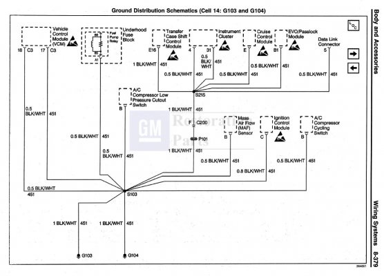
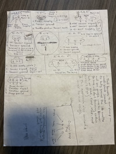
In this first diagram I tried to group the reported failures by category. For example, most of the DTCs had to do
with 'out of band too low' signals from the sensors. The one exception was the P0463, which was a too high voltage
for the Fuel Level sensor? And this failure was consistently reported, no matter the status of the purple wire?
You must be registered for see images attach
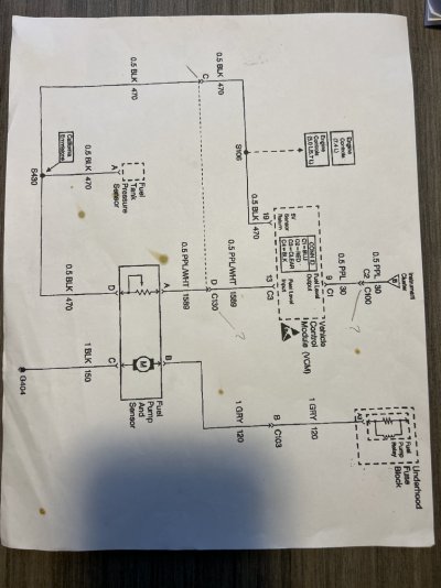
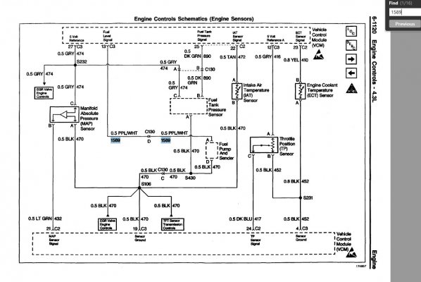
This second page is where I spent most of my time. I was looking for shared power sources or sensor grounds that would
help to explain so many similar DTCs for these engine sensors:
You must be registered for see images attach
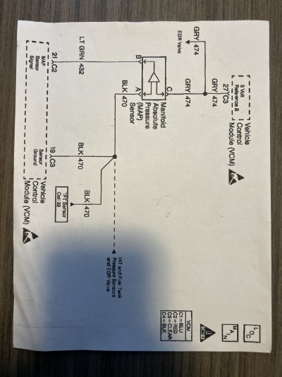
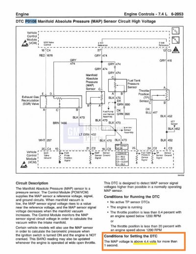
And for those who ever wondered how the design engineers could determine that a constantly
varying analog signal is good vs a spurious signal from a open or shorted path, this is done by
forcing the signal to stay specified limits. This way, once the computer detects a voltage that's
either too close to either the +5v Reference or Ground, it can reliably declare an electrical failure.
Pretty neat:
You must be registered for see images attach
That's all I've got for now. Now that we've organized the DTCs by failure pattern, hopefully this will help us
narrow down where the intermittent connection(s) are in this engine bay.
Here's hoping that some of the other talent in this forum can take some of this 1st-pass failure analysis,
find any mistakes I've made, and take this to the next level. It doesn't make a lot of sense to me at
this time, but no doubt that it will once the problems are found and fixed.
Happy Hunting. Best of luck --


 Did you mean the MAP sensor?