Fuel gauge sending wire disconnected= normal engine performance?

Disclaimer: Links on this page pointing to Amazon, eBay and other sites may include affiliate code. If you click them and make a purchase, we may earn a small commission.

phantom 309

I'm Awesome
Joined
Jan 17, 2018
Messages
103
Reaction score
86
Location
?
Eagle eye, @phantom 309! Multiple sets of eyes reading for comprehension is what makes this
forum the strength that it is. I appreciate you studying the contents of this thread so carefully.

I'm going to edit/correct that posting now so that it's a better resource for future reference.

Well done, sir. :waytogo:
aw gosh,.glad to help? a little,. I might be tempted to peek inside the vcm myself for possible corrosion,. and as for driveability maybe disconnect the egr,. to see if it help/cures, the off idle stumble.
i'm maybe going to ask for help my self soon in a new thread,.
 

phantom 309

I'm Awesome
Joined
Jan 17, 2018
Messages
103
Reaction score
86
Location
?
Yeah… not really.

What most people call “ground” is actually a multitude of parallel, relatively low impedance paths.

The only mistake in your statement is that some paths have relatively higher impedance than others, and that’s where unexpected problems can arise.

This may go against intuition, but it’s the truth :waytogo:
i would agree in aircraft and other machinery with delicate instruments and varying power and ground needs,.
but,. i am not so sophisticated or smart,. and a 25+ yr old obs, in my experience, works much better with as much ground(s) as can, regardless oft times of the ground location
and grounding straight to cast or steel,. and not to aluminum,.works better for me,. YRRMV
 

1998_K1500_Sub

Nitro Junkie
Supporting Member
Joined
Jan 28, 2019
Messages
2,871
Reaction score
4,449
Location
Rural Illinois
a 25+ yr old obs, in my experience, works much better with as much ground(s) as can, regardless oft times of the ground location

Good morning!

One thing that’s interesting to note is that GM has two and possibly three isolated grounds on the GMT400, C17,18 and C19 and C4. Their only common connection is at the ECU.

Notably, they run a separate ground all the way back to the fuel sensor, they don’t ground it at the chassis.
 
Last edited:

Keeper

Supporting Member
Supporting Member
Joined
Dec 6, 2020
Messages
781
Reaction score
1,905
Location
Northern Virginia
Wow, you guys are impressive

Just throwing a thought out. The 98's have a fuel tank pressure sensor, and the P0452 code was thrown which could indicate a bad ftp sensor. Not certain, but I thought they only worked when tank was neither full nor empty (15-85%). He said that the truck runs noticeably worse with a full tank than with a 1/2 tank. Was that sensor replaced with the fuel pump/sender, and is the wiring with it and the sender kosher? I think it is also heavily involved with EVAP/EGR functions. (99 FSM3 6-1972)

edit: also, my 98 454 is in shop for a/c work, but my 99 454 (01/99) has the same grounds as @Road Trip ... nothing extra on G103
 
Last edited:

Schurkey

Supporting Member
Supporting Member
Joined
Jan 14, 2018
Messages
12,548
Reaction score
16,266
Location
The Seasonally Frozen Wastelands
grounding straight to cast or steel,. and not to aluminum,.works better for me,.
Iron and steel are crappy conductors compared to aluminum--provided the aluminum is kept relatively corrosion-free at the contact points.

Copper is better-still than aluminum, and silver is pretty-much king.

Which is why you see silver-plated copper wire, copper-plated aluminum wire, actual aluminum wire in high-tension power lines, and nobody makes electrical cables out of steel, although they may make structural cables from steel.
 

Road Trip

Supporting Member
Supporting Member
Joined
Jul 8, 2023
Messages
1,669
Reaction score
4,739
Location
Syracuse, NY
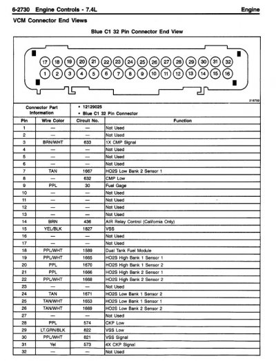
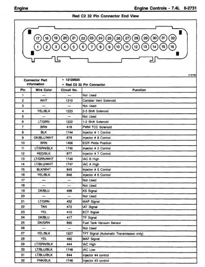
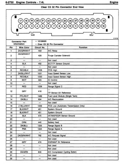
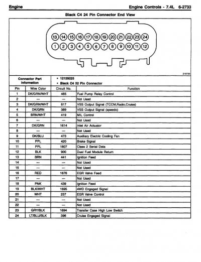
Alright, we've identified the small cluster of grounds that the VCM relies upon as the electrical
foundation in order to reliably manage his '98 drivetrain on behalf of the driver. (While
simultaneously keeping the emissions within the limits of it's EPA calibration.)

From this point forward, in order to keep the dialog moving, for troubleshooting
purposes I'm going to make the assumption that the OP has inspected/tested/verified that
these grounds are good. (ie: The OP has tested the grounds per reply #40.)

****

In subsequent replies I am going to focus on other areas of relevant circuits. In particular,
if you go back to reply #22 & review the DTCs that are kicked, the biggest group of failures
are all centered on the sensor data signals going out of bounds too low. To me this indicates that
we are experiencing a droop/loss of the +5v reference voltage, not losing the opposing sensor
ground.

So, in order to support the verification of signal paths to/from the VCM, in the attachments
I've posted all 4 connectors for the VCM. (C1=Blue, C2=Red, C3=Clear, C4=Black) In addition,
I've attached a .pdf file of these same 4 pages so that the OP & others can easily blow these up
in order to easily read them.

FWIW I'm working on a possible theory based upon what's identified in the truck vs what's in the
'98 FSM wiring diagrams. On debug projects like this, the first win is always the hardest (due to
all the necessary preparation) ...but once we get the first circuit to start working, the rest of the
problems will be easier. Just gotta work our way through a few outer layers of this problem onion...
 

Attachments

  • '98 VCM Connector C1 end view - 1998_GMT-98_CK-4_SERVICE_MANUAL-VOLUME_4_of_4-1.jpg
    '98 VCM Connector C1 end view - 1998_GMT-98_CK-4_SERVICE_MANUAL-VOLUME_4_of_4-1.jpg
    146.2 KB · Views: 8
  • '98 VCM Connector C2 end view - 1998_GMT-98_CK-4_SERVICE_MANUAL-VOLUME_4_of_4-1.jpg
    '98 VCM Connector C2 end view - 1998_GMT-98_CK-4_SERVICE_MANUAL-VOLUME_4_of_4-1.jpg
    156.2 KB · Views: 8
  • '98 VCM Connector C3 end view - 1998_GMT-98_CK-4_SERVICE_MANUAL-VOLUME_4_of_4-1.jpg
    '98 VCM Connector C3 end view - 1998_GMT-98_CK-4_SERVICE_MANUAL-VOLUME_4_of_4-1.jpg
    156.6 KB · Views: 8
  • '98 VCM Connector C4 end view - 1998_GMT-98_CK-4_SERVICE_MANUAL-VOLUME_4_of_4-1.jpg
    '98 VCM Connector C4 end view - 1998_GMT-98_CK-4_SERVICE_MANUAL-VOLUME_4_of_4-1.jpg
    127.7 KB · Views: 8
  • '98 VCM connector end views.pdf
    812.3 KB · Views: 1
Last edited:

Road Trip

Supporting Member
Supporting Member
Joined
Jul 8, 2023
Messages
1,669
Reaction score
4,739
Location
Syracuse, NY
Additionally, the truck runs poorly at idle. Interestingly, if I cut the purple sending unit wire at the fuel pump, the truck runs perfectly, though it throws multiple codes, including:

Okey-dokey, I've been trying to figure out how connecting/disconnecting the fuel level sensor could affect
the driveability of your vehicle. One detail that caught my eye is that you mentioned on a couple of
occasions that you were manipulating a 'purple' wire. Problem is, the '98 FSM documents a PPL/WHT
wire between the sensor in the tank and the VCM. (I've noticed that sometimes a VCM-related wire
will have a white stripe added to it -- for example, the 2 VCM "System Ground" black ground wires
at pins 17/18 on connector C3 have a white stripe added. (!)

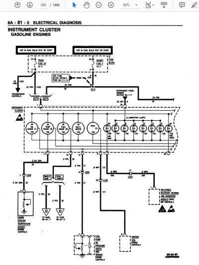
Along these lines, there was a change that occurred around the '98 timeframe was that on gas engine
GMT400s the fuel gauge was no longer driven directly by the fuel sender in the gas tank. Instead, in
order to enable the VCM to monitor/test the Evaporative Emissions subsystem, the fuel sensor was
now connected to the VCM, and then in turn the VCM drives the fuel gauge.

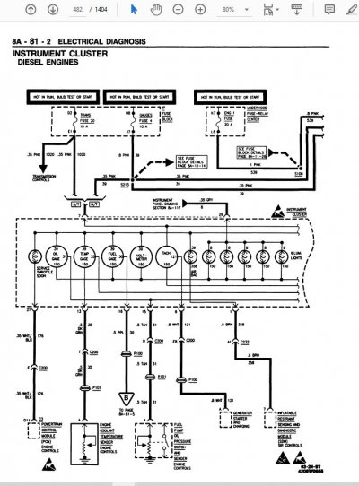
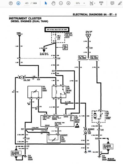
Guess what? According to the '98 FSM, the diesel equipped GMT400s did *not* connect their fuel
level sending unit to the PCM? (aka: Diesel ECU) After studying the 2 FSM pages that document the
diesel fuel level circuit, a PPL wire was still routed between the sensor in the tank and the gauge in the
dash:

You must be registered for see images attach


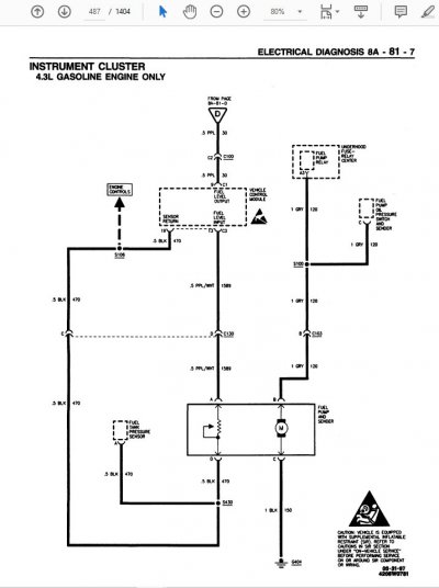
For comparison purposes, here is my hand-drawn 'everything on 1 page' for the gasoline powered '98 GMT400s:

You must be registered for see images attach


NOTE: In reply #19 you described a splice that you discovered between the fuel sensor return and the fuel tank pressure sensor, which you followed up
on by observing the same thing in treasure yard vehicles:
Yes, I did open all the looms up to the ECM and found a set of wires spliced together near the fuel tank. This included the sending ground signal wire for the sending unit and the tank pressure sensor ground. Initially, I thought this was the cause of all my problems. To verify, I checked three trucks at the junkyard, dropping their fuel tanks to compare their wire harnesses and splices. Surprisingly, I found that all three had identical wiring and splices, with black tape used from the factory.

According to what I found in the FSM, you have physically located 'S430' as seen in the circuit above.
Like you surmised, this is a circuit feature, not a fault.

****

OK. Given the above I think that something went sideways in this area *prior* to you purchasing this
K3500 in Spokane and easing it down to San Diego. Is it possible that some unknown mechanic tried
to connect your gas fuel level sender directly to the instrument cluster gauge (old school style) instead
of doing it the '98+ correct way?

Saying it technically, is the output of the fuel level sending unit connected to PPL circuit #30 instead of
the PPL/WHT of circuit #1589? And by doing so, is this somehow loading down either the +5v reference
or the sensor return? (Notice that the Diesel fuel level sensor grounds back to G104, while the gas fuel
level sensor circuit relies upon circuit #470, which terminates at sensor ground pin 19 C3?)

The above is the highest probability, but being remote for all I know this truck was originally built with a
Diesel powerplant under the hood, and a big block was swapped in with *most* of the factory L29 wiring
harness? Of course your wiring may be correct and we've stumbled across yet another documentation
error ("PPL/WHT") in the FSM, but whenever something doesn't match up I always take this as a hint
to dig a little deeper in order to get a better idea of what exactly is going on, if you know what I mean.

****

If this was my truck, I would do my very best to figure out EXACTLY where that PPL wire ends up being
connected to. And if I couldn't make sense of it in my lifetime, I wouldn't hesitate to install a fresh path
for circuit #1589 (PPL/WHT) to the proper pin on the VCM. (My working theory is that the direct connection
from the sending unit to the gauge would then also be cross-connected to the fuel gauge output from the VCM,
and this in turn creating the weirdness affecting the VCM functionality globally? I'd also verify the sensor ground
is robust, and then I'd expect that the fuel gauge to start working properly AND no longer kick those saggy
voltage DTCs on the previously affected sensors?

NOTE: Working solo it's quite possible that errors have crept into my hand drawn 'big picture' diagrams.
Therefore, in the next reply I will post the FSM pages that I was working from.

Hope this proves helpful. At the very least it might give either you or one of the folks reading along some
additional ideas. Given how many things can be goofed with since your truck lumbered off the assembly line,
any/all of the above is possible, even if rarely observed in the wild.

Best of luck with your hunt. If you happen to find the smoking gun, be sure to take pics and share them
here for the benefit of others who are also driving around in electrical Funkytown.

Cheers --
 
Last edited:

Road Trip

Supporting Member
Supporting Member
Joined
Jul 8, 2023
Messages
1,669
Reaction score
4,739
Location
Syracuse, NY
Here are the FSM pages to support the hand-drawn stuff in reply #58.

The first 2 attachments are for the Diesel fuel level circuit, beginning to end.

Attachments #3 and #4 are for the gasoline fuel level circuit, also beginning to end.

As always, the devil is in the details. Can't wait to find out what the OP discovers, for
the reported symptoms are well off of the beaten path. :0)
 

Attachments

  • '98 diesel gauge p1of2 - 1998_GMT-98_CK-1_SERVICE_MANUAL-VOLUME_1_of_4.jpg
    '98 diesel gauge p1of2 - 1998_GMT-98_CK-1_SERVICE_MANUAL-VOLUME_1_of_4.jpg
    128.5 KB · Views: 6
  • '98 Diesel gauge p2of2 - 1998_GMT-98_CK-1_SERVICE_MANUAL-VOLUME_1_of_4.jpg
    '98 Diesel gauge p2of2 - 1998_GMT-98_CK-1_SERVICE_MANUAL-VOLUME_1_of_4.jpg
    105.7 KB · Views: 8
  • '98 gas gauge VCM p1of2 -- 1998_GMT-98_CK-1_SERVICE_MANUAL-VOLUME_1_of_4.jpg
    '98 gas gauge VCM p1of2 -- 1998_GMT-98_CK-1_SERVICE_MANUAL-VOLUME_1_of_4.jpg
    118.5 KB · Views: 3
  • '98 gas gauge VCM p2of2 - 1998_GMT-98_CK-1_SERVICE_MANUAL-VOLUME_1_of_4.jpg
    '98 gas gauge VCM p2of2 - 1998_GMT-98_CK-1_SERVICE_MANUAL-VOLUME_1_of_4.jpg
    72.1 KB · Views: 3
Last edited:

2jduenas

Newbie
Joined
Jun 28, 2023
Messages
27
Reaction score
20
Location
San Diego Ca.
### Summary of Updates and Actions Taken:


1. **Fuel Level Gauge Working:**

- Successfully got the fuel level gauge working for the first time since owning the truck.


2. **Sensor Diagnostics:**

- Focused on DTC P0463, which affects other DTCs.

- Located the ECM plug and checked resistance with it unplugged:

- No continuity between pin 19 and either pins 17 or 18.

- 0.1 ohm reading between pins 17 and 18.

- Checked resistance before with the plug connected to the ECM and had caught continuity between the 3 pins.


3. **Wire Snipping and Jumping:**

- Since there was no resistance between the small black wire and the purple wire, I snipped the black wire away from the run and splices a few inches back from the plug.

- Jumped a wire from the snipped wire to the fuel pump harness, connecting it with the fuel tank pressure signal ground, and the fuel pump level sensor signal ground.


4. **Results:**

- Everything worked, and there were no present codes.


5. **New Codes:**

- reconnected this new wire that I ran to the run that I snipped away from the plug and new codes popped up: P01007, P0452, P1107 so I disconnected it. Note that during this test the fuel gauge remained working and truck performance was unchanged. I ended this test and left myself with only the straight run (jumper)


6. **Fuel Level Sending Unit:**

- Drove to a gas station, filled up, and the gauge moved to full.

- The truck ran well with a full tank, with no more bogging and bucking.

- Drove the truck under load, and the check engine light came back on.

- Only one code (P0101) appeared.


### Current Situation:

- I am now left with only one code (P0101).

- Considering two options:

1. Inspect the looms and find all the splices connected to the signal ground.

2. Run new signal grounds to each sensor associated with pin 19.


Reasons:

1. **Inspecting the Looms:**

- This approach allows me to identify and address any faulty splices or connections.

- It can be time-consuming but ensures I find any underlying issues within the existing wiring.


2. **Running New Signal Grounds:**

- This could be a quicker solution but involves running new wires, when I may not need to.

- Ensures a fresh and potentially more reliable connection for each sensor


### Next Steps:

1. **Inspect Looms:**

- Check for any damaged wires, poor splices, or connections.

- Repair any issues found and re-test the system.


2. **Run New Grounds (if needed):**

- If the issue persists, run new signal grounds to ensure each sensor connected to pin 19 has a reliable ground.


By following these steps, I should be able to address the P0101 code and ensure the reliable operation of the truck’s sensors and fuel level gauge.


Your thoughts?
 
Top