### Next Steps:
1. **Inspect Looms:**
- Check for any damaged wires, poor splices, or connections.
- Repair any issues found and re-test the system.
2. **Run New Grounds (if needed):**
- If the issue persists, run new signal grounds to ensure each sensor connected to pin 19 has a reliable ground.
By following these steps, I should be able to address the P0101 code and ensure the reliable operation of the truck’s sensors and fuel level gauge.
Your thoughts?
Hello 2jduenas,
Your detailed writeup is appreciated. Over the years I've fixed my way out of electrical warning harness issues
in a couple of different ways. It depends upon the situation, so I'll try to clarify below.
1) From hard-won experience I've learned that a wiring harness and a head of lettuce have a lot in common.
That is, the edges go bad first, but the center can stay good for much longer. Given this, I have no problem
repairing the existing wiring harness on the tattered edges as needed, as opposed to completely swapping out
the entire wiring harness just in order to fix one or more tough intermittents. IMHO, the 'new' harness is very
labor intensive, both in the treasure yard as well as the problem vehicle, and it's also too easy to introduce
new errors during installation. :-(
2) If I'm on the side of the road/long way from home and I've troubleshot to a bad wire, I won't
hesitate to substitute a new length of wire for the bad one in order to get me home.
Also, if the vehicle is in it's last salt season and will be cheerfully retired the following spring, then I'll run a
new wire as a temporary fix with no regrets. (Mindset = I'm not looking for more trouble, I just want
to fix what's known bad and get back asap to the crisis du jour. :0)
3) If I'm troubleshooting in my shop and I discover a bad spot in the harness and/or a burnt connector,
I'll take the time to inspect/test/repair the existing harness. (Mindset = I am going to repair what's bad,
and while I'm in there I am going to take the initial failure as a warning that I need to proactively look for
more trouble in the harness, and not hesitate to fix anything I find.) Especially if I'm working on a 'keeper'
or 'forever' vehicle. I've never regretted a careful fix that it still working years later. :0)
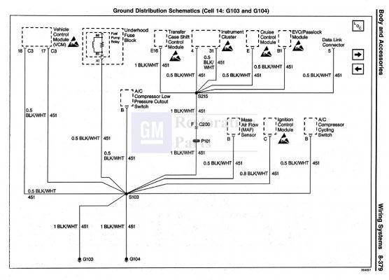
And your comment about ensuring good grounding between pin 19 C3 and all associated sensors is a solid approach.
The bottom line, the more solid your ground and power distribution system, the way more rational that
all your sensors will be acting (from the VCM's perspective) ...making your electrical troubleshooting life
down the road with this vehicle that much more straightforward. Making your power
and grounds robust
is time invested instead of just time spent. (!)
And you have just proven this by what you've accomplished in your reply #60.
****
Re: The remaining P0101 DTC. I'd like to dig into that a little more before commenting.
P0101 = Mass Air Flow (MAF) sensor performance. Many a parts blunderbuss has been
loaded with a new MAF right after the computer throws a P0101, with no improvement
afterwards. (!)
In order to try & reason our way through a P0101 popping up after so many other DTCs
have been cleared, we need to read the (5) pages in the FSM for this code before changing
any parts. The first thing we need to do is to understand *why* the VCM decided to kick
this code. (!)
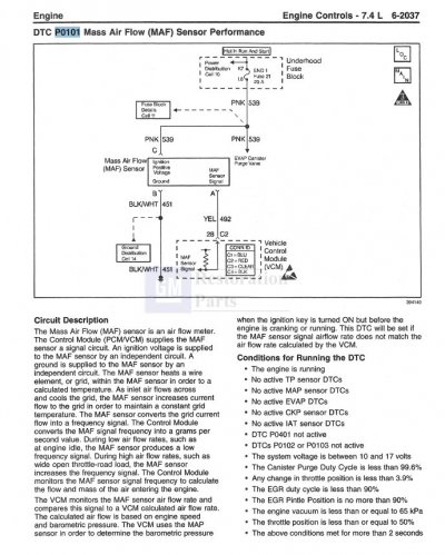
Quoting the FSM: Conditions for setting the DTC -- "The actual MAF value is not equal to
the
calculated value for more than 5 seconds."
Now, according to the FSM, the VCM uses the inputs from the TPS and the MAP in order
to come up with the calculated value. The book explicitly warns that a bad TPS sensor
can cause a miscalculation. Also, if the MAP sensor output is out of tolerance ("skewed")
then the VCM could be basing it's MAF calculation on an inaccurate BARO reading, again
creating an erroneous calculated MAF value to compare the real one against. (In other
words, a false indictment.)
So at this point, we need to keep in the back of our mind that the VCM is reliant upon good
MAP & TPS readings (plus +12v MAF, +5v Ref TPS & MAP, sensor signals, and sensor ground
wiring) in order to come up with something to correctly compare/judge the actual MAF sensor's
functionality. (!)
****
So the above describes the why. But why now? Did fixing the original wiring issue somehow
cause the P0101?
Under the "Conditions for Running the DTC", there's a long list of conditions that must be met
before the P0101 DTC is allowed to run. Here's a shorter list that's related to our situation:
*
DTCs P0102 and P0103
not active (MAF low, MAF high)
* No active MAP DTCs
* No active EVAP DTCs
In other words, the P0101 MAF Performance test was inhibited from running while related DTC
failures were already occurring. So on a vehicle suffering from a long-term multi-DTC failure,
once the original problem is fixed, it's quite possible for a (previously latent) failure to bubble
up and again set the SES light & kick a fresh code.
****
Once our previous methods fail to make further progress on these newer failures, now what?
OK. This is key. Before going any futher, ensuring that the MAF enjoys the same robust
power and sensor ground connections as the other sensors is a given. In addition, there's
a specific mention for this DTC having to do with interference from other systems:
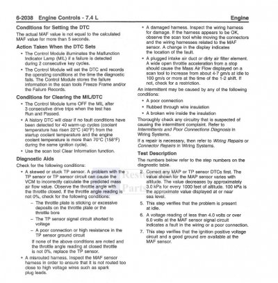
"A misrouted harness. Inspect the routing of the MAF harness to ensure that it doesn't come
too close to high voltage wires such as spark plug leads."
And who knows? You might find an additional wiring fault where fixing the same will clear the
P0101 DTC. If so, great!
But IF not, then a careful reading of the P0101 section of the FSM tells us that input data
from the sensors specified in the troubleshooting flows is key to figuring this out. And they
reference the use of a Scan Tool in order to look at the values of the signals related to the
kicking of the DTC P0101.
****
So here we are now at a troubleshooting threshold. By focusing on the commonality of all the
DTCs being kicked, that eventually lead you to finding/fixing a wiring fault. By doing so,
now the DTC 0101 was allowed to run, and it now flagged as an error.
The troubleshooting question you need to answer is:
* Is the MAF actually bad and is the
perpetrator of the failure?
* Is the MAF actually good and is the
victim of the VCM misidentifying
the MAF as bad. If so, is the VCM being misled by a skewed input from
either sensor it's using for it's calculations/comparison? Or are the other
sensors good and the wiring to the VCM is sketchy? Or (worst-case scenario)
the VCM has an internal component failure and is incapable of getting it right?
Q: How to we figure this out prior to replacing parts?
A: Carefully studying the live data via employing a scan tool capable of sharing
the necessary data.
NOTE: Others have used the parts cannon. Actually, this will work IF you get a
(good) new part and the original MAF was the perpetrator of the failure. On the
other hand, all the times you read about a $$$ MAF swap and no improvement?
That's the case where the MAF was the
victim of being misidentified as the problem,
so obviously replacing a good part with another good part isn't going to give us any
repair traction? FWIW, here's a thread about a MAF being swapped out but no joy.
Unfortunately this thread dead-ended prematurely: (
MAF swap, but no joy)
To summarize all this, MAF sensors do go bad. If after the wiring guru {you} verifies
that your MAF enjoys the same good power, ground, and signal connectivity that the
Fuel Level Sensor now enjoys, it's time to up our troubleshooting game and take it to
the live data level.
Note: If you have access to a free, 100% known-good/flown-good MAF, then you can swap this
in and get a quick go/no-go answer. Please note that I did not say a "new MAF", for today's
troubleshooter knows that new parts are just another unknown which must be proven good/bad
before relying upon it. (!)
Assuming that a known-good MAF isn't available, then let's look at what the existing MAF, TPS,
and MAP sensors are putting out. With live data, we actually get to look over the VCM's shoulder
and see what it's interpretation of reality is.
And if you haven't already picked your own OBD-2 scan tool out, then say so, and others can
chime in with what's worked out best for them.
And if you post those readings here, then I will commit to getting the same data from my 'known good'
'99 454 C2500. This way if you are getting similar readings as I, then we can back-burner those areas
and focus elsewhere. But if we get a mismatch, then we'll investigate that until we can explain why...with
the ultimate goal of changing only the part(s) that are directly contributing to the P0101 DTC.
****
For what it's worth, I'm looking forward to you getting this truck to run with -0- DTCs. You have made
significant progress since the 16th -- I can almost smell the finish line from here. :0)
PS: Revelant FSM pages:
'98 FSM P0101 section: p. 6-2759<>6-2762 ;your year truck
'99 FSM P0101 section: p. 6-2037<>6-2041 ;similar to '98 writeup, with improved Circuit Description (See first 2 pages in attached.)