Fuel gauge sending wire disconnected= normal engine performance?

Disclaimer: Links on this page pointing to Amazon, eBay and other sites may include affiliate code. If you click them and make a purchase, we may earn a small commission.

Road Trip

Supporting Member
Supporting Member
Joined
Jul 8, 2023
Messages
1,669
Reaction score
4,740
Location
Syracuse, NY
I don't know about you, but I'm thinking the VCM sensor ground circuit needs to be checked in detail:

From your comments I can tell that we are thinking along the same lines, troubleshooting-wise. No doubt
that normal parts replacement can't fix what ails this particular vehicle. And the OP mentioned that he had
a couple of mechanics look at this, as well as the fact that you can tell from his troubleshooting notes that
he has dug into this more than most would have. When someone is trying this hard to solve a tough problem
it really makes me want to help in any way possible. (!)

This reminds me of a crank-no-start problem I debugged on a Dodge pickup.

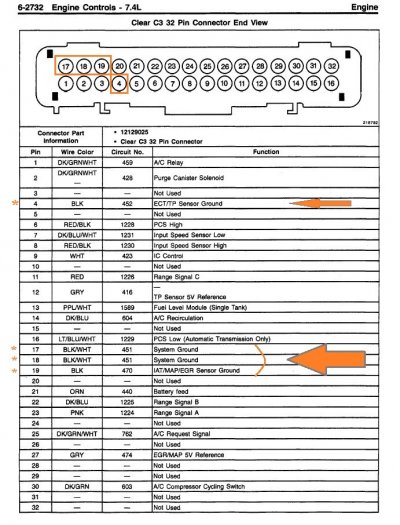
In that case, the VCM's power ground (which is the VCM's ground connection to the chassis) was open-circuit. The VCM was half-alive tho, as it was using its sensor ground circuit as its power ground... which worked well enough for it to appear sane, but which was insufficient when the VCM tried to fire the injectors.

Take-away / To-do: Check the VCM power ground to the chassis. Do this by disconnecting all connectors to the VCM and then measuring the resistance between the relevant pins in the VCM harness and ground at the engine block.

This should measure ~0.2Ω.

Finally, check the VCM's internal connection it provides between chassis ground and sensor ground. With the VCM's four(?) connectors disconnected, measure across the relevant pins of the VCM (sensor ground, chassis ground) and confirm ~0.2Ω.

@2jduenas, in order to get an even better idea of how a marginal ground can allow partial operation of a computer-controlled
system, take a moment and read what 1998_K1500_Sub wrote: (Engine starts but dies after engine swap)

Just to set expectations, a straightforward 'bad sensor on a good wire' failure may take an evening or two to troubleshoot. A single completely
open or shorted wire that is known to fail (due to a known stress/design issue) can take a week or so (evenings after the day job) to track down if
the failure is hidden under the dash or behind the engine. Especially if your mentor is remote instead of working shoulder-to-shoulder
under the hood.

But when it comes to a 'marginal' ground, this can take a lot of time. Especially when there's a flurry of associated symptoms,
DTCs, etc. These kinds of failures force us to get the books out, develop theories, and then test the theories and learn from
the results.

And since the OP has tried multiple fuel level sensors and even tried swapping out the VCM, I think that everything here points
to testing/repairing/verifying the signal paths as Nitro Junkie is recommending.

****

As for test equipment, I believe in a measured response:

1) If the computer can detect an anomaly (SES light + DTC code) then I try to clear that first.
2) If the factory troubleshooting process for that DTC can be performed using a DVM, then proceed with that.
3) On the other hand, as soon as the factory troubleshooting process recommends using a Scan Tool that will show real time data, then of course we must step up our game.
4) And if there is no SES light and yet the vehicle still isn't running right, then of course you need to monitor live data in order to see what the computer is reacting to/being fed by it's sensors.
5) And if the (VCM A/D processed) live data still can't shed enough light on the problem, then ultimately looking at the raw signals with a scope may be required.

NOTE: This is a comprehensive troubleshooting approach when a completely stock engine bay is being worked on. Obviously once a non-stock tune, 0411 upgrade,
or nonstock engine parts are employed, then all bets are off, and the sky's the limit. :0)

For what it's worth, this is the approach we used on our aging F-16s when we had a stubborn malfunction like this where no amount of
black box swapping was going to right the wrong. And although we used terms like like 'MFLs' and 'T.O. Library', the actual process was much
the same -- sometimes we would reach the end of the troubleshooting fault trees and still no joy.

And this was when we would stop, develop one or more theories, and then employ a 2nd 'known good' jet for comparison purposes.
(Didn't happen often, but I still remember these episodes clearly.)

Given the above, if we get to a spot where a 'known good' GMT400 might help us figure out stuff that's beyond what is in the FSMs,
I'll be happy to try and duplicate those engine bay measurements on my '99 454 C2500. (Obviously a known-good '98 engine bay would
be even better, but something is better than nothing.)

More in a bit. Going to compare '98 vs '99 VCM <> engine grounding -- I think that a change was implemented between the years, but
want to confirm this before continuing.
 
Last edited:

1998_K1500_Sub

Nitro Junkie
Supporting Member
Joined
Jan 28, 2019
Messages
2,871
Reaction score
4,449
Location
Rural Illinois
I'll be away for the rest of the week until next Monday, so my comments will be terse, if any.

I think you're on the right path :waytogo:
 

2jduenas

Newbie
Joined
Jun 28, 2023
Messages
27
Reaction score
20
Location
San Diego Ca.
Hello everyone,

Thank you for all of your responses, and I apologize for the delay in updating. I have been trying my best to allocate as much time as possible to resolve this issue. Here is a summary of my progress so far:

1. Engine Harness Diagram: Thanks to the engine harness diagram provided by Road Trip, I found a hidden ground wire (G104) taped into a loom. After moving the radiator hose, I saw that the stud had no wire connected to it. I couldn’t find any dangling wire, so I opened the loom running across the EGR and found a black wire tucked away. It seemed as if someone had snipped it and tucked it away, thinking it wasn’t important.

2. Premature celebration: Although I reconnected and secured the wire, this did not resolve the issue. The DTCs remained unchanged. After driving the truck with about half a tank of gas for around 5 miles, the check engine light came on. The truck struggled slightly on acceleration. After filling the tank, the truck bucked and bogged down, forcing me to disconnect the purple wire to get back home. The codes thrown during this drive were P0101 and P0463.

3. Continuity Test: I performed a continuity test on the purple wire, which checked out fine. Concerned about a potential short in the large loom near the fuse box, I snipped the purple wire a few inches back from the ECM plug, reset all DTCs, and repeated the tests. With the key on and engine off, the computer displayed P0452 and P0463. After running the truck for 10 minutes, additional codes (P0107, P0405, and P0452) appeared, indicating circuit low DTCs. Disconnecting the small black wire sending ground didn’t change the DTCs.

4. Fuel Level Sensor: I did some digging and found this in the manual

“The Fuel Level sensor is an important input to the Vehicle Control Module (VCM) for the Enhanced Evaporative System Diagnostic. The VCM needs the fuel level information in order to know the volume of fuel in the tank. The fuel level affects the rate of change in the air pressure in the EVAP system. Several of the Enhanced Evaporative System Diagnostic sub-test are dependent upon the correct fuel level information. The diagnostic will not run when the tank is greater than 85% or less than 15% full. (This sensor signal disables the misfire when the fuel levels are less than 15%). This DTC is a type D DTC.”

Is this telling us something?, I believe the issue is related to the proper reading of the fuel level. If the sensor is not reading correctly, it will continue to trigger these DTCs. I plan to pull apart the dash tomorrow to trace the wires from the cluster to the ECM to check for any suspicious activity.

Hope to have updates for y’all soon. Thanks again to all of you. It is awesome to know Awesome people! The few times that I took this truck to the mechanics, it was very disappointing as it only took five minutes of me explaining just a portion of what I’ve tried doing to fix this issue to see that they had already given up on the job before they started.
 

1998_K1500_Sub

Nitro Junkie
Supporting Member
Joined
Jan 28, 2019
Messages
2,871
Reaction score
4,449
Location
Rural Illinois
So now you know for a fact, somebody’s f’d with the electrical system.

:waytogo:

All you need to do now is restore it.

I’m sorry I haven’t got time to craft a detailed response to your post. Busy day, busy week.
 

Road Trip

Supporting Member
Supporting Member
Joined
Jul 8, 2023
Messages
1,669
Reaction score
4,740
Location
Syracuse, NY
As per usual, if you could pay close attention to each and every ground going to the VCM this would be a good starting point.

@Road Trip, where does the VCM sensor ground attach? My Suburban isn't nearby so I can't check, but IIRC there the VCM sensor ground is via two wires that connect via a single ring terminal to a stud on or near the coolant neck on the intake.

Of the 4 connectors on the VCM, only Connector #3 has any ground connections.
Furthermore, all 3 4 grounds are grouped closely together. Check out this Connector end view:

You must be registered for see images attach

(from 1998 FSM)

More specifically, to answer your question pin 19 on C3 is the sensor ground. (circuit #470)
Note: I just rechecked what I drew back in reply #22, and it's correct.


And in this wiring diagram you can see where 17 & 18 C3 are tied to G103 & G104:
You must be registered for see images attach

(from 1998 FSM)


So on the VCM end, we have accounted for all grounds. Now to pull up where G103 & G104 are physically located:

You must be registered for see images attach

(from 1998 FSM)

****

I understand that this may seem a bit like documentation overkill on the ground plane between the VCM, the engine, and also the sensors.

But we are literally laying a solid foundation for all the rest of the electrical troubleshooting we will be doing from this point forward. Once
we have inspected/tested/verified all the grounds involved, everything else is just layering on lower functions, followed by higher functions.

In my humble opinion, the more test equipment we have on site (thinking scan tools that record real time data and high resolution oscilloscopes)
...the less we have to fuss over the basics like ground planes...for if the signals are ugly looking we would know to stop and make all the
connections like brand new. But since we're starting this expedition with the basics, we really need to know exactly where to look for trouble,
and in an abundance of caution, verify that all connections are still in new condition. :0)

****

Your latest status report came in while I was documenting the VCM <> Engine & sensor ground paths, so I will post this and then
read your reply.

FWIW --
 

Attachments

  • '98 VCM Connector C3 end view (ground arrows corrected) - 1998_GMT-98_CK-4_SERVICE_MANUAL-VOLU...jpg
    '98 VCM Connector C3 end view (ground arrows corrected) - 1998_GMT-98_CK-4_SERVICE_MANUAL-VOLU...jpg
    227.7 KB · Views: 14
Last edited:

2jduenas

Newbie
Joined
Jun 28, 2023
Messages
27
Reaction score
20
Location
San Diego Ca.
Of the 4 connectors on the VCM, only Connector #3 has any ground connections.
Furthermore, all 3 grounds are grouped closely together. Check out this Connector end view:

You must be registered for see images attach

More specifically, to answer your question pin 19 on C3 is the sensor ground. (circuit #470)
Note: I just rechecked what I drew back in reply #22, and it's correct.


And in this wiring diagram you can see where 17 & 18 C3 are tied to G103 & G104:
You must be registered for see images attach


So on the VCM end, we have accounted for all grounds. Now to pull up what G103 & G104
are physically located:

You must be registered for see images attach


****

I understand that this may seem a bit like documentation overkill on the ground plane between the VCM, the engine, and also the sensors.

But we are literally laying a solid foundation for all the rest of the electrical troubleshooting we will be doing from this point forward. Once
we have inspected/tested/verified all the grounds involved, everything else is just layering on lower functions, followed by higher functions.

In my humble opinion, the more test equipment we have on site (thinking scan tools that record real time data and high resolution oscilloscopes)
...the less we have to fuss over the basics like ground planes...for if the signals are ugly we would know to stop and make all the
connections like brand new. But since we're starting this expedition with the basics, we really need to know exactly where to look for trouble,
and in an abundance of caution, verify that all connections are still in new condition. :0)

****

Your latest status report came in while I was documenting the VCM <> Engine & sensor ground paths, so I will post this and then
read your reply.

FWIW --
Trust me none of this is overkill. It is all very much needed detail for this hunt. I appreciate all of it and will study it this evening.
 

2jduenas

Newbie
Joined
Jun 28, 2023
Messages
27
Reaction score
20
Location
San Diego Ca.
So now you know for a fact, somebody’s f’d with the electrical system.

:waytogo:

All you need to do now is restore it.

I’m sorry I haven’t got time to craft a detailed response to your post. Busy day, busy week.
No worries at all. The support here has been incredible; this is a fantastic forum. Unfortunately, yes the truck has definitely been tampered with. On a positive note, this situation has given me the opportunity to become very familiar with the truck, which brings me a sense of satisfaction.
 

1998_K1500_Sub

Nitro Junkie
Supporting Member
Joined
Jan 28, 2019
Messages
2,871
Reaction score
4,449
Location
Rural Illinois
Of the 4 connectors on the VCM, only Connector #3 has any ground connections.
Furthermore, all 3 grounds are grouped closely together. Check out this Connector end view:

So if OP takes an ohmmeter and picks any two of those three pins (C17, C18, C19) he should see low impedance between them. I suggest he check the impedance in this way, for all three combinations of the three pins measured two at a time.

If I am correct, in 1996 and 1997 there was actually a TSB which discussed the ground problem of this very type in the VCM, I.e., the internal ground in the VCM, between C19 and the other two C17 & C18, would fail and become an open circuit.


You must be registered for see images attach

More specifically, to answer your question pin 19 on C3 is the sensor ground. (circuit #470)
Note: I just rechecked what I drew back in reply #22, and it's correct.


And in this wiring diagram you can see where 17 & 18 C3 are tied to G103 & G104:
You must be registered for see images attach


So on the VCM end, we have accounted for all grounds. Now to pull up where G103 & G104
are physically located:

^^^ Well done.

So on the 454 the two grounds G103 and G104 are physically distinct.

That’s interesting, because they share a common node S103 further upstream, so it just forms a ground loop… but it’s a high current circuit, it’s not a sensor circuit, so it evidently isn’t material in this case.

The sensor ground only has one node in common with the other grounds, and that node resides in the VCM, accessible on pin C19. Makes sense.

Fun stuff!
 
Last edited:

2jduenas

Newbie
Joined
Jun 28, 2023
Messages
27
Reaction score
20
Location
San Diego Ca.
So if OP takes an ohmmeter and picks any two of those three he should see low impedance between them. I suggest he do so.

If I am correct, in 1996 and 1997 there was actually a TSB which discussed the ground problem of this very type in the VCM, I.e., the internal ground in the VCM would open circuit.


^^^ Well done.

So on the 454 the two grounds G103 and G104 are physically distinct.

That’s interesting, because they share are common node further upstream, so it just forms a ground loop… but it’s a high current circuit, it’s not a sensor circuit, so it evidently isn’t material in this case.

The sensor ground only has one node in common with the other grounds, and that node resides in the VCM, accessible on pin C19. Makes sense.
Thanks, I will check the 2 pins in the morning, can you clarify how I am to do this, would I back probe with plug installed or removed from from ECM? Also if performed with plug installed should key be on engine off ect. And would it make sense to reconnect purple wire?
 

1998_K1500_Sub

Nitro Junkie
Supporting Member
Joined
Jan 28, 2019
Messages
2,871
Reaction score
4,449
Location
Rural Illinois
Thanks, I will check the 2 pins in the morning, can you clarify how I am to do this, would I back probe with plug installed or removed from from ECM? Also if performed with plug installed should key be on engine off ect. And would it make sense to reconnect purple wire?

Remove the ”C” connector from the ECU and probe the ECU pins directly with a DVM.

By the way, if you have not removed that ground connection to the chassis at the fuel sender using the small black wire, you should do so now or very soon. That connection should be eliminated.

It sounds to me like that connection, the small black wire at the fuel sender which is a sensor ground connection to ECU pin C19, was actually functioning as a system ground in lieu of G103 and G104. How exactly that was happening isn’t yet clear to me. I know you have found at least one ground connection (G103 or G194, yes?) that was not in place.
 
Last edited:
Top