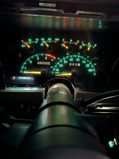
Moonie to needle cluster swap

Disclaimer: Links on this page pointing to Amazon, eBay and other sites may include affiliate code. If you click them and make a purchase, we may earn a small commission.

someotherguy

Even more awesome in person
Joined
Sep 28, 2013
Messages
11,009
Reaction score
17,641
Location
Houston TX
I have soldered a couple of times but never on a circuit board. I am a little nervous about it because I will lose my mind if I booger up my circuit board!! Any tips/advice on this is always appreciated!!
It's pretty easy. I've been soldering since I was a little kid, using my Pawpaw's Craftsman soldering gun which was an enormous, bulky thing - hooking up stuff on a model railroad set. These days one can learn by simply watching a few youtube videos.

One very important thing to remember is you want rosin core (electronics) solder, not acid core (plumbing) - and while a temperature-controlled soldering iron is nice, it's probably more money than you'd want to spend for just one or two small jobs.

You need to de-solder the fuses, which means not only getting them off the circuit board but also clearing the thru-holes of solder so that you can place the DIP switch in for soldering. A de-soldering iron is the easiest way to do this, IMO. I still use one I bought at Radio Shack probably 25 years ago. They're inexpensive. You can also use a regular soldering iron in conjunction with a solder sucker tool, but that's a two-handed job instead of one, as you need to heat the solder joint with the iron and then immediately remove it with the sucker tool before it hardens again.

PRACTICE.. on some old junk electronics first. A busted old cheap radio from the thrift store, something like that, with similar electronics - "thru hole" components is what you're looking for, not all this surface mount modern stuff.

Richard
 

Redsled

Newbie
Joined
Apr 4, 2022
Messages
34
Reaction score
36
Location
Charlotte, NC
Thank you Richard! I was planning to practice on a junkyard circuitboard!

What about flux? Do you recommend using it?
 

someotherguy

Even more awesome in person
Joined
Sep 28, 2013
Messages
11,009
Reaction score
17,641
Location
Houston TX
Thank you Richard! I was planning to practice on a junkyard circuitboard!

What about flux? Do you recommend using it?
Never needed it with rosin core solder, on the work I've done, and I've done a lot. Hobby is collecting/repairing classic arcade games and pinball machines, and a lot of that entails re-soldering a bazillion cracked solder joints on late 70's/early 80's vintage stuff.

Any other repairs aside, this was roughly 350 solder joints that needed to be re-done on the header pins for the harness connections on this boardset, from a 1980 pinball machine called "Firepower" by Williams Electronics:
You must be registered for see images attach


Richard
 
Last edited:

Redsled

Newbie
Joined
Apr 4, 2022
Messages
34
Reaction score
36
Location
Charlotte, NC
I solder the dip in. But something isn’t right. My speedometer is still way off. First, i need to make sure I soldered the DIP in correctly. The 91 circuit board is slightly different versus the Moonies.

Here are two pictures one of the front one of the back. One thing I am wondering is - is the left row the one that should be all connected? Did i do that part backwards? The left row was the “solid” one with the factory fuses….but seems opposite of the moonies?
 

Attachments

  • IMG_7325.jpeg
    IMG_7325.jpeg
    406.3 KB · Views: 9
  • IMG_7326.jpeg
    IMG_7326.jpeg
    421.1 KB · Views: 9

Redsled

Newbie
Joined
Apr 4, 2022
Messages
34
Reaction score
36
Location
Charlotte, NC
For reference this is a picture of the back before I removed anything. The “solid” row is on the left hand side.
 

Attachments

  • IMG_7317.jpeg
    IMG_7317.jpeg
    491.3 KB · Views: 10

someotherguy

Even more awesome in person
Joined
Sep 28, 2013
Messages
11,009
Reaction score
17,641
Location
Houston TX
Those two rows of thru-holes are the same trace. It's duplicated for the purpose of fitting two potential different sizes of parts.

Is that picture in post #45 from the back, your "finished" install??

Richard
 

Redsled

Newbie
Joined
Apr 4, 2022
Messages
34
Reaction score
36
Location
Charlotte, NC
Those two rows of thru-holes are the same trace. It's duplicated for the purpose of fitting two potential different sizes of parts.

Is that picture in post #45 from the back, your "finished" install??

Richard
Yes that picture is my finished install. Hopefully I didn’t screw this up!
 

89RCLB

Old Dudes Rule
Supporting Member
Joined
Feb 21, 2017
Messages
1,208
Reaction score
1,284
Location
Falcon, CO
Remove that white calibration clip that is sticking out of the back of the circuit board, you no longer need it.
 

someotherguy

Even more awesome in person
Joined
Sep 28, 2013
Messages
11,009
Reaction score
17,641
Location
Houston TX
Yes that picture is my finished install. Hopefully I didn’t screw this up!
I see some very bad solder joints. A few of the pins don't even really seem to be connected.

Remove that white calibration clip that is sticking out of the back of the circuit board, you no longer need it.
VERY good catch. I looked right past it. I knew they existed but since they're obsolete at this point, I'd never even touched one, and the whole idea of installing a DIP switch is to avoid the scenario of having to obtain and use the programming clip.

Redsled: that white plastic programming clip was GM's solution for re-calibrating the speedo. Voltage is applied to blow all those fuses that were originally installed, and then the programming clip is set as jumpers to effect the new settings. The clip being a one-shot deal like the fuses, I still say the DIP switch is the way to go.

Unfortunately, it also means any readings you took from your fuses after removal are null and void. They should have all read "open" ..

Remove that clip as he said (it just pulls out of the socket), look at the tables in the article, and set the switches according to your tire height and axle ratio.

Richard
 
Top