Aluminum alloy.my intake is pure aluminum
But so is the TBI intake. No meaningful difference.


Disclaimer: Links on this page pointing to Amazon, eBay and other sites may include affiliate code. If you click them and make a purchase, we may earn a small commission.
Aluminum alloy.my intake is pure aluminum
Also check engine light does stay on with key on btw
I'm definitely gonna double check my engine grounds but is pin 14 the red connector on the ECM or the blue one in not familiar with the pin outs assigned numbers yet
Okay cool so hopefully it's still good for grounding what it needs toAluminum alloy.
But so is the TBI intake. No meaningful difference.
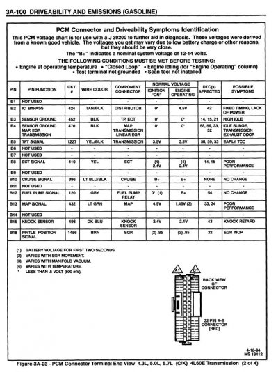
So on the diagram it shows that the B pin is supposed to have 5v but mine shows almost 10 and when I tested ground on the A pin it showed good but didn't zero out do you know what might cause that?That's actually good news, for there have been instances across the internet where
it was a long & arduous process for someone to just get their SES (GM's check engine light)
to illuminate. So the first step (of many) has been achieved. Now to get PCM pin A14 grounded
and see those flashing codes appear.
Here's some valuable navigation info courtesy of the '95 FSM.
There are 16 pins per alpha prefix:
A1 - A16 RED connector
B1 - B16 RED connector
E1 - E16 BLUE connector
F1 - F16 BLUE connector
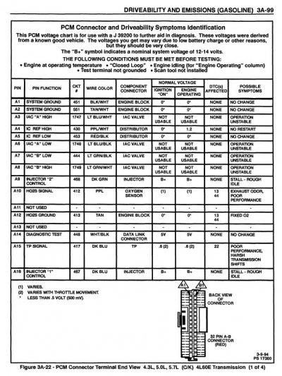
Knowing this, now take a look at this PCM illustration and see this info now stands out on the
righthand side of the page:
You must be registered for see images attach
(NOTE: No C or D alpha prefixes for the pinning? Anyone ever find out why in their travels?)
****
I had a moment, so to finish drawing the big picture, PCM pin-wise, I chose the non-big block / 4L60-E
pinouts and attached them to this reply. If it was me, I would print these out and tape them to the
wall above my workbench for quick referencing. (Or put them in a 3-ring binder.) For this would allow
me to speed up the verification of all the wiring that is involved in the engine swap.
****
Learning how to extract all the navigational info out of the wiring diagrams is very similar to learning how to extract
the same thing from a road map. In either scenario, it's really frustrating in the beginning. But with some practice,
these navigational tools go from part of the problem to part of the solution.
And if you haven't already done so, you need to fill your project map pocket with the Factory Service Manuals
covering your vehicle. ('88+ GMT400 FSM download links)
Necessity is the mother of invention. I encourage you to see this engine swap through to completion, no
matter the stumbling blocks you encounter along the way. For if you get through the first one or two of these
projects, in exchange for the late night tears of frustration during the project you will enjoy the positive
reinforcement that comes from driving around in something you brought back to life. And this is kinda like Basic
Training for everything else in your life. You are better for the experience.
At least that's how it worked out for yours truly. :0)
Best of luck with the hunt --
Also I don't know if I forgot to mention but my truck is equipped from factory with 5.7 TBI 350 and 4l80e I don't know if that would make a difference on the diagrams but either way the information has helped because now Im able to at least test for continuity on those specific wires also I don't for sure know how to test for shorts in the wires so if anyone can tell me how to do that I'd appreciate itThat's actually good news, for there have been instances across the internet where
it was a long & arduous process for someone to just get their SES (GM's check engine light)
to illuminate. So the first step (of many) has been achieved. Now to get PCM pin A14 grounded
and see those flashing codes appear.
Here's some valuable navigation info courtesy of the '95 FSM.
There are 16 pins per alpha prefix:
A1 - A16 RED connector
B1 - B16 RED connector
E1 - E16 BLUE connector
F1 - F16 BLUE connector
Knowing this, now take a look at this PCM illustration and see this info now stands out on the
righthand side of the page:
You must be registered for see images attach
(NOTE: No C or D alpha prefixes for the pinning? Anyone ever find out why in their travels?)
****
I had a moment, so to finish drawing the big picture, PCM pin-wise, I chose the non-big block / 4L60-E
pinouts and attached them to this reply. If it was me, I would print these out and tape them to the
wall above my workbench for quick referencing. (Or put them in a 3-ring binder.) For this would allow
me to speed up the verification of all the wiring that is involved in the engine swap.
****
Learning how to extract all the navigational info out of the wiring diagrams is very similar to learning how to extract
the same thing from a road map. In either scenario, it's really frustrating in the beginning. But with some practice,
these navigational tools go from part of the problem to part of the solution.
And if you haven't already done so, you need to fill your project map pocket with the Factory Service Manuals
covering your vehicle. ('88+ GMT400 FSM download links)
Necessity is the mother of invention. I encourage you to see this engine swap through to completion, no
matter the stumbling blocks you encounter along the way. For if you get through the first one or two of these
projects, in exchange for the late night tears of frustration during the project you will enjoy the positive
reinforcement that comes from driving around in something you brought back to life. And this is kinda like Basic
Training for everything else in your life. You are better for the experience.
At least that's how it worked out for yours truly. :0)
Best of luck with the hunt --
Also I don't know if I forgot to mention but my truck is equipped from factory with 5.7 TBI 350 and 4l80e I don't know if that would make a difference on the diagrams but either way the information has helped because now Im able to at least test for continuity on those specific wires
also I don't for sure know how to test for shorts in the wires so if anyone can tell me how to do that I'd appreciate it
So on the diagram it shows that the B pin is supposed to have 5v but mine shows almost 10 and when I tested ground on the A pin it showed good but didn't zero out do you know what might cause that?
You must be registered for see images attach
The main spark table is based on MAP and RPM, so similar to a carb'd engine with vacuum and mechanical advance. But it has modifiers for coolant temp as well. If it had an IAT, which speed density does, then there'd be modifiers there as well. But for some reason I have it in my head these TBI engines got by without.
Thank you I will check all that tomorrow when I got some more daylight and I'll let you know what I find the thing sounds healthy when it idles so I can't bring myself to give up especially since the problem is probably simple once I find it and I'm more than likely gonna be kicking myself for the following year once I find it but again thank you guys so much also I can't seem to find the diagrams like the ones you guys have sent, is there a specific website where I can locate the diagrams specific to my truck?Yes, when looking for technical assistance it's always best to share the year, model, and drivetrain, for
it can make a difference. I started comparing the 4L60 vs 4L80 pinouts, ran into a couple of differences,
started heading down the rabbit hole.
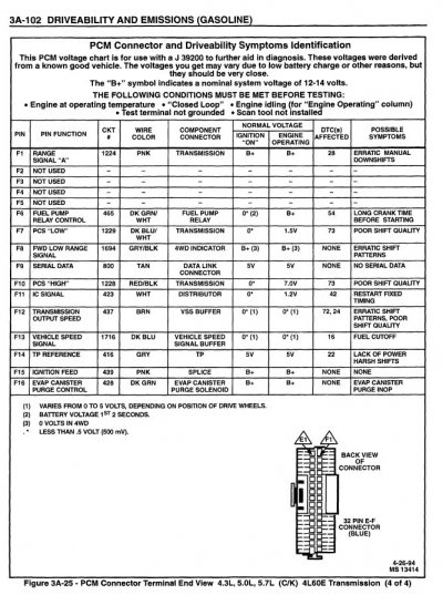
Then I decided to bundle up the (4) 'PCM w/4L80-E pinouts pages into a .pdf file and attach it to this reply. This
gives you a much sharper image, easy to print, easily blown up, etc.
This is pretty straightforward. Let's set aside the PCM and instead test the wires feeding the headlights.
When the wires are good there is continuity between the light switch in the cabin and the lights themselves,
but when you check for continuity between the wire and ground there is no continuity. (Note: With the light
disconnected so that that we aren't measuring the path through the filament to ground.) Continuity between
a power wire and ground will normally cause sparking, followed by the associated fuse blowing. If you've ever
owned a car that had ate fuses (especially when it rained or you drove it over rough terrain) then it's likely
that the vehicle had one or more chafes between the wiring harness & ground.
But checking the continuity without moving the wiring harness around is not a thorough check. You need to
gently move the wiring harness around in order to simulate what happens on a rough road -- a short to
ground is usually where movement causes rubbing that develops into a chafe through the insulation.
A bit harder to find is a chafe between unrelated wires in the harness, usually caused by the harness is
pinched, bound too tight, or the harness was stressed in a manner that the engineers didn't anticipate.
(Think motor flopping around due to a loose/bad motor mount, constantly tugging on the harness.)
Finally, if the PO added in an alarm system, CB radio, etc., a lot of times you will find some custom wiring
that create shorts to ground that can make a good vehicle blow fuses at the worst possible times.
Essentially, you don't want continuity between unrelated wires for obvious reasons. Think of a beat down truck
where the horn blows when the headlights come on. Or windshield wipers that start running when the fan is
turned on. Usually we only start checking for cross-wire chafes when really weird symptoms occur.
I would write that down in case we need to come back to this and explore further, but for now I'd like you
to jumper a good ground to pin A14 and see if you can't get the SES light to start flashing codes. (At least a
repeating '12', indicating no stored codes.) If you jumper a ground directly to the Diagnostic Test pin and the
SES light starts flashing, but won't do so when you jumper Pin A to Pin b in the DLC connector, then there's an
open in the wire between the two and you need to track that down.
Once we get the SES light operational, then the next step will be to get the serial data pin working. Once you
have access to the PCM Codes and the live data, then getting the ignition spark advance working will just be
more of the same.
If the above doesn't make complete sense just keep asking questions until we end up on the same page.
Best of luck --