Help, adding a fuel pump cutoff

Disclaimer: Links on this page pointing to Amazon, eBay and other sites may include affiliate code. If you click them and make a purchase, we may earn a small commission.

808_c1500

Newbie
Joined
Jun 8, 2022
Messages
28
Reaction score
12
Location
Honolulu. Hawaii
IMO. The quickest, easiest way to make the pump not run is to put a switch in the hot line that feeds the pump. Everything will work as designed but the fuel pump will not run until the circuit is completed when you close the switch
Makes sense... do you know the best and easiest location to tap my switch into power to the pump? I don't want to run a lot of wire to get it into the cab/dash area....also what gauge is best if I'm tying into the hot line? I'm not very knowledgeable at wiring..but trying to learn. Everyone has been super helpful.
 

Road Trip

Supporting Member
Supporting Member
Joined
Jul 8, 2023
Messages
1,725
Reaction score
4,878
Location
Syracuse, NY
You'll need to go up further so the Oil Pressure Switch doesn't turn on the Fuel Pump as well.

Astute observation!

Can you tell me more? If I switch off one of the two wires I listed, won't that make the fuel pump inoperable and the starter just crank without any fuel? How does the oil pressure switch make the fuel pump still work if the fuel pump relay is essentially off?

Greetings 808_c1500,

I found the exact same wiring diagram you posted in the '88 Electrical FSM, so the following are taken from the same manual.

First, @PlayingWithTBI is giving you the big picture of the power delivery to the fuel pump. There are not 1 but 2
power sources wired in parallel, so either one can fire up the fuel pump. (If the engine oil pressure switch is the only
one working, this will normally lead to longer cranking times before starting...but it will eventually start. (!)

Here's the big picture, power-wise. Look carefully for splice S114, for this is where you want your switch to go in
order to shut off all sources of power to the fuel pump:

You must be registered for see images attach

(from the '88 Electrical FSM)

In the attached I've included the page where the physical location of S114 is described.

For what it's worth, I like the approach of disabling the fuel delivery yet still allowing the
engine to crank over. This will give the impression that the vehicle is not running right
(& being less interesting to take) vs. the starter not responding and giving the immediate
clue to look for a anti-theft kill switch.

Tip of the hat to PlayingWithTBI for letting you know that disconnecting too close to the
fuel pump relay will only disable one side of the power feed into the fuel pump. What's outlined
above should give you the control over unauthorized fuel pump operation that you are
looking for. (NOTE: The ECM is also disabled, so no fuel + no spark, but still cranks =
best reasonable effort security disabling.)

Hope this proves helpful with your implementation.
 

Attachments

  • '88 S114 physical location -- '88_ST-375-88-EDM_GM_CK_PICK-UP_TRUCK_ELECTRICAL_DIAGNOSIS_SUPPL...jpg
    '88 S114 physical location -- '88_ST-375-88-EDM_GM_CK_PICK-UP_TRUCK_ELECTRICAL_DIAGNOSIS_SUPPL...jpg
    281.2 KB · Views: 9

PlayingWithTBI

2022 Truck of the Year
Supporting Member
Joined
Jan 3, 2019
Messages
10,414
Reaction score
16,852
Location
Tonopah, AZ
Look carefully for splice S114, for this is where you want your switch to go in
order to shut off all sources of power to the fuel pump:
I was looking there too but, IDK what would happen if you kill power to the ECM too. that may reset it every time you kill the pump - maybe not. If it was me, I'd disconnect the 2 GRN wires going to the OPS and FPR.

OP - if you look at the numbers on the left of the wires, in this case #1, others are .8 most of the time. That's the metric (mm2) size for them. Then look it up here. IMO 16ga will be sufficient since GM has a tendency to under size their wires.
www.1xtechnologies.com/mm-to-awg/


808_c1500

Newbie
Joined
Jun 8, 2022
Messages
28
Reaction score
12
Location
Honolulu. Hawaii
@Road Trip, thank you for your insight!

OK, so @PlayingWithTBI's suggestion sounds like a good option..maybe I can use one switch for both OPS and FPR depending on location.

However, I only see DARK GRN/WHT from ECM and no other green for the OPS.

Can i cut off the 2 orange wires to OPS and FPR right after the S114 splice?
 
Last edited:

Road Trip

Supporting Member
Supporting Member
Joined
Jul 8, 2023
Messages
1,725
Reaction score
4,878
Location
Syracuse, NY
I was looking there too but, IDK what would happen if you kill power to the ECM too. that may reset it every time you kill the pump - maybe not.

This is why I like the way that one of us can make a suggestion, and then it gets kicked around (peer reviewed)
in here. I thought that I had covered the 'continuous power feed for the volatile memory' issue...but upon looking
closer I think I've uncovered an error in the '88 FSM?

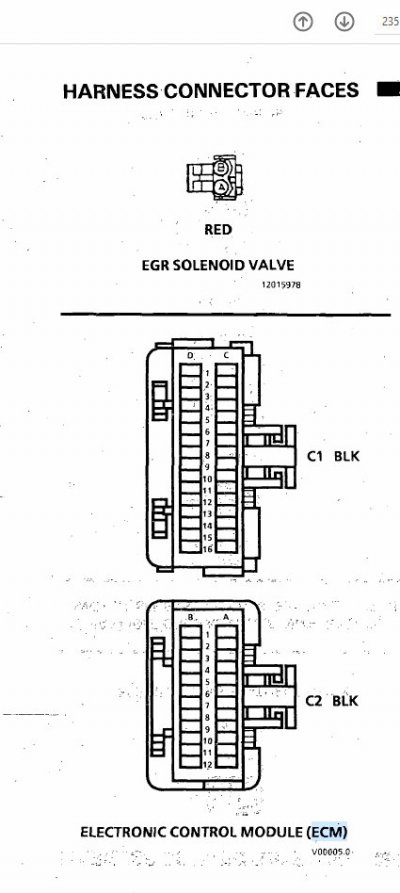
Check this out -- look for the oval where I circled the (documented) input for the continuous battery power:

You must be registered for see images attach


OK, if I take it at face value, Pin A6 on Connector C2 covers the continuous power so that all the local self-tuning (& SES error codes) aren't lost.
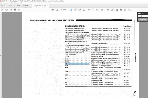
And going back to my last post, removing power before splice S114 affects:

* C16 on Connector C1
* B1 on Connector C2

Looking at the ECM connector pinout page (see attached) I saw no conflict, so I posted reply #12.

HOWEVER, based upon your comment I went back and took a closer look. Sure enough, I see an
error in the diagram above. In order to provide the claimed 'continuous battery input for memory'
functionality, Pin A6 on connector C2 must be connected to a "Hot At All Times" wire. (Which is
typically color coded orange.) But the diagram above is showing a pink/black wire leading back to
a feed from the ignition switch via the ECM/IGN fuse?


****

As Schurkey has mentioned elsewhere, there were so many errors in the new '88 model FSMs that they
subsequently printed a Supplement. Given all this, I'm siding with your proposed solution in reply #15.

And I'm going to leave my reply #12 in place, for I think this illustrates for others that these books are
very good to excellent...but they aren't perfect. 36 years later there is an irreducible noise floor in these
books, but as long as we pay close attention to this fact, then we can still eventually hammer out a correct
solution.

Summarizing, reply #15 could be implemented with a DPDT switch? (DPDT switch selection) NOTE: All
wiring for this hidden switch will be entirely inside the cab, reducing weatherproofing issues.

Whew -- learned a lot more in this area than I anticipated. :0)
 

Attachments

  • '88 ECM connector pinout - '88_ST-375-88-EDM_GM_CK_PICK-UP_TRUCK_ELECTRICAL_DIAGNOSIS_SUPPLEMENT.jpg
    '88 ECM connector pinout - '88_ST-375-88-EDM_GM_CK_PICK-UP_TRUCK_ELECTRICAL_DIAGNOSIS_SUPPLEMENT.jpg
    65.2 KB · Views: 9
Last edited:

PlayingWithTBI

2022 Truck of the Year
Supporting Member
Joined
Jan 3, 2019
Messages
10,414
Reaction score
16,852
Location
Tonopah, AZ
This is why I like the way that one of us can make a suggestion, and then it gets kicked around (peer reviewed)
in here. I thought that I had covered the 'continuous power feed for the volatile memory' issue...but upon looking
closer I think I've uncovered an error in the '88 FSM?
Nice catch! It can't be both continuous and switched, LOL. It looks like a simple test would be, with ignition off, hit the brake pedal and see if the lights come on. IIRC they do. So, you do have power to the C2 connector but, what about the C1?

Summarizing, reply #15 could be implemented with a DPDT switch? (DPDT switch selection)
I don't think a DPDT switch is needed since the feed wires are already connected so, there's no need to keep them separate here.
 

95burban

Friends don’t let friends use spindles.
Joined
Apr 23, 2022
Messages
1,393
Reaction score
3,215
Location
Tx
You can also ground your “tach” wire. Look next to your ignition coil and you will find a white wire with a black terminal, you can run a wire from that terminal to a hidden switch. When the switch it flipped it grounds the coil.
 
Top