Additionally, the truck runs poorly at idle. Interestingly, if I cut the purple sending unit wire at the fuel pump, the truck runs perfectly, though it throws multiple codes, including:
Okey-dokey, I've been trying to figure out how connecting/disconnecting the fuel level sensor could affect
the driveability of your vehicle. One detail that caught my eye is that you mentioned on a couple of
occasions that you were manipulating a 'purple' wire. Problem is, the '98 FSM documents a PPL/WHT
wire between the sensor in the tank and the VCM. (I've noticed that sometimes a VCM-related wire
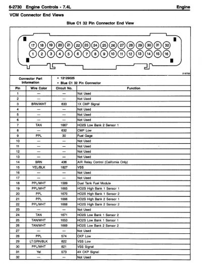
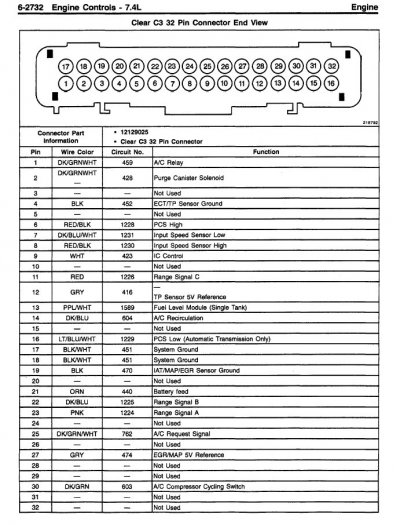
will have a white stripe added to it -- for example, the 2 VCM "System Ground" black ground wires
at pins 17/18 on connector C3 have a white stripe added. (!)
Along these lines, there was a change that occurred around the '98 timeframe was that on gas engine
GMT400s the fuel gauge was no longer driven directly by the fuel sender in the gas tank. Instead, in
order to enable the VCM to monitor/test the Evaporative Emissions subsystem, the fuel sensor was
now connected to the VCM, and then in turn the VCM drives the fuel gauge.
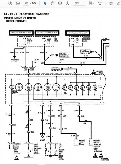
Guess what? According to the '98 FSM, the diesel equipped GMT400s did *not* connect their fuel
level sending unit to the PCM? (aka: Diesel ECU) After studying the 2 FSM pages that document the
diesel fuel level circuit, a PPL wire was still routed between the sensor in the tank and the gauge in the
dash:
You must be registered for see images attach
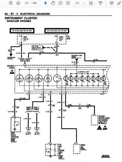
For comparison purposes, here is my hand-drawn 'everything on 1 page' for the
gasoline powered '98 GMT400s:
You must be registered for see images attach
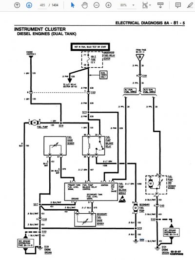
NOTE: In reply #19 you described a splice that you discovered between the fuel sensor return and the fuel tank pressure sensor, which you followed up
on by observing the same thing in treasure yard vehicles:
Yes, I did open all the looms up to the ECM and found a set of wires spliced together near the fuel tank. This included the sending ground signal wire for the sending unit and the tank pressure sensor ground. Initially, I thought this was the cause of all my problems. To verify, I checked three trucks at the junkyard, dropping their fuel tanks to compare their wire harnesses and splices. Surprisingly, I found that all three had identical wiring and splices, with black tape used from the factory.
According to what I found in the FSM, you have physically located 'S430' as seen in the circuit above.
Like you surmised, this is a circuit feature, not a fault.
****
OK. Given the above I think that something went sideways in this area *prior* to you purchasing this
K3500 in Spokane and easing it down to San Diego. Is it possible that some unknown mechanic tried
to connect your gas fuel level sender directly to the instrument cluster gauge (old school style) instead
of doing it the '98+ correct way?
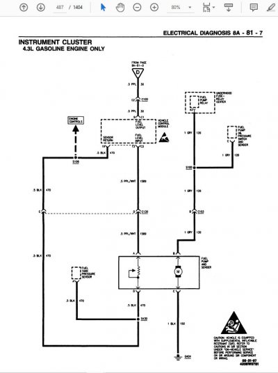
Saying it technically, is the output of the fuel level sending unit connected to PPL circuit #30 instead of
the PPL/WHT of circuit #1589? And by doing so, is this somehow loading down either the +5v reference
or the sensor return? (Notice that the Diesel fuel level sensor grounds back to G104, while the gas fuel
level sensor circuit relies upon circuit #470, which terminates at sensor ground pin 19 C3?)
The above is the highest probability, but being remote for all I know this truck was originally built with a
Diesel powerplant under the hood, and a big block was swapped in with *most* of the factory L29 wiring
harness? Of course your wiring may be correct and we've stumbled across yet another documentation
error ("PPL/WHT") in the FSM, but whenever something doesn't match up I always take this as a hint
to dig a little deeper in order to get a better idea of what exactly is going on, if you know what I mean.
****
If this was my truck, I would do my very best to figure out EXACTLY where that PPL wire ends up being
connected to. And if I couldn't make sense of it in my lifetime, I wouldn't hesitate to install a fresh path
for circuit #1589 (PPL/WHT) to the proper pin on the VCM. (My working theory is that the direct connection
from the sending unit to the gauge would then also be cross-connected to the fuel gauge
output from the VCM,
and this in turn creating the weirdness affecting the VCM functionality globally? I'd also verify the sensor ground
is robust, and then I'd expect that the fuel gauge to start working properly AND no longer kick those saggy
voltage DTCs on the previously affected sensors?
NOTE: Working solo it's quite possible that errors have crept into my hand drawn 'big picture' diagrams.
Therefore, in the next reply I will post the FSM pages that I was working from.
Hope this proves helpful. At the very least it might give either you or one of the folks reading along some
additional ideas. Given how many things can be goofed with since your truck lumbered off the assembly line,
any/all of the above is possible, even if rarely observed in the wild.
Best of luck with your hunt. If you happen to find the smoking gun, be sure to take pics and share them
here for the benefit of others who are also driving around in electrical Funkytown.
Cheers --