
Hunter2024
Newbie
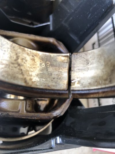
Hi, this is my first engine rebuild on a chevy c1500 4.3 vortec with the internal balance shaft, and I got a little carried away when tearing it down and did not mark the connecting rods and caps when I removed them. They have a dimple on them which I assume is to face them the correct way but I'm not sure which way on which bank. I also believe I mixed up the direction of the caps when i slid them back together for storage because some of the bearings have the slit on the same side and some of them have them on opposite sides. Can someone please help?
You must be registered for see images attach
You must be registered for see images attach
You must be registered for see images attach
You must be registered for see images attach