
I have no brake lights, no gas gauge, no oil or temp sensor.
What did you end up figuring out? I'm in the same problem your in right now and would like some advise
There is a lot of information in these. But I couldn't find anything about a wire or connector behind the glove box
Greetings Blackcat84357,
The original poster's last visit to the forum was only a couple of weeks after posing his question, so he
hasn't been here in quite some time. But as mentioned in previous replies, figuring out the differences
between these 2 harnesses is possible, but only if you are familiar with how the data about the electrical
subsystems is organized. So let's start there.
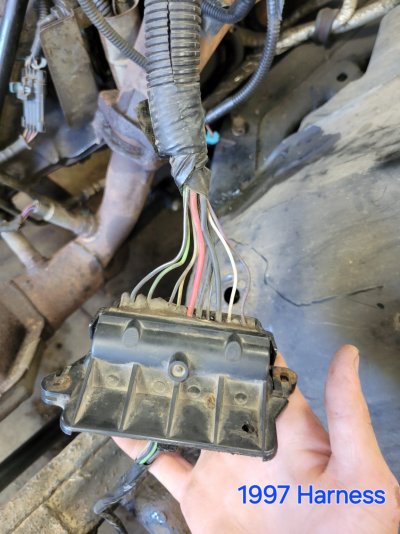
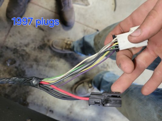
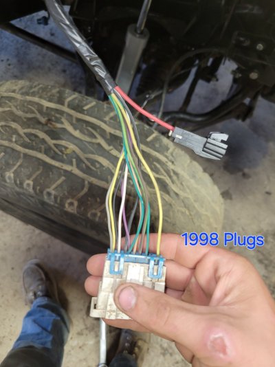
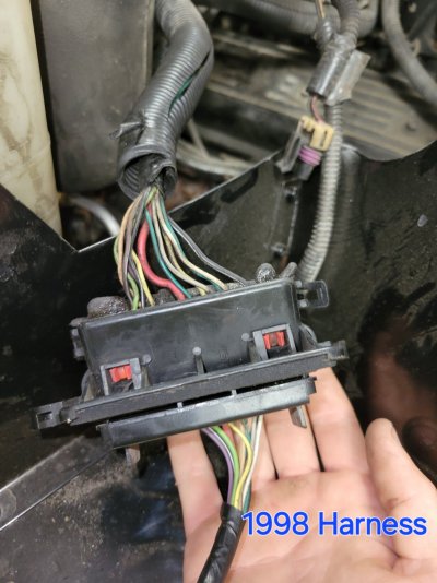
First of all, @Erin's comment about pictures of the connectors in questions are a big help when matching
what you have physically to the Connector End Views in the Factory Service Manuals. A sharp side view
showing the attached color-coded wires would be the most helpful.
As for the FSMs, the electrical wiring harness physical layout as shared by @east302 is in there, and this
is valuable info once we know which functional circuits we are dealing with. But in order to figure out which
disconnected wires go where, we need to know their functionality, for this is how the info you need is
organized.
For example, the OP stated that "I have no brake lights, no gas gauge, no oil or temp sensor."
After a bit of sifting through the '98 ('99) manuals, I was able to attach the unique circuit (CKT) numbers to each broken function:
* Brake lights (Stop Lamps) CKT #140 ORN
* Gas Gauge - CKT #30 PPL
* Oil Pressure Gauge - CKT #31 TAN
* Temp Gauge - CKT #35 DK GRN
Between your description of the general connector location and combining this with the illustration shared by
East302 above, I searched for the C200 Connector End View/pinout info, and came up with this:
You must be registered for see images attach
Note that we have a Brake Pedal Switch output, Oil Pressure & Coolant Temp wires listed in the pinout,
so this is looking pretty promising. But in order to take this example from an educated guess to a confirmed hit,
clear, focused pictures of the connectors(s) you are researching would be a necessary cross-check.
And once we really know which connector(s) you have in hand (by comparing your pics to Connector End Views)
this is when you get the '96 & '98 Electrical sections opened up and start following where specific electrical circuits
are routed. Just like a jigsaw puzzle, building a cross-reference table will be slow going at first, but as
you start to get all the wires for the missing functions accounted for, it will all fall together neatly.
Disclaimer: There is no guarantee that the above is the correct answer for your wiring issue. However, this
is a good example of how to go about taking the failure data that you have in hand and using it to help you
figure out where to look in the Factory Service Manuals for the pinout/wiring data you'll need to finish the swap.
Hope you find this helpful. Let us know what you discover.
And good on you for being willing to put in the time & effort to keep another one of these old warriors on the road.
Cheers --
PS: Welcome to the GMT400 forum. You have located the place on the internet where folks help each other where
they can in order for us all to be able to keep enjoying this generation of the General's full size trucks & SUVs.
Last edited: