Zimmerly
OBS Enthusiast
If I need to, can I jump the orange wire from a key-on wire, using an in-lin fuse, if I need to get to work in a pinch and figure it out tomorrow? ...if NEED BE anyway?
Last edited:


Disclaimer: Links on this page pointing to Amazon, eBay and other sites may include affiliate code. If you click them and make a purchase, we may earn a small commission.
If I need to, can I jump the orange wire from a key-on wire, using an in-lin fuse, if I need to get to work in a pinch and figure it out tomorrow? ...if NEED BE anyway?
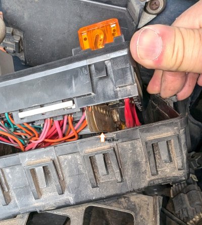
Back again. For sunset's sake, I jumped the constant hot wire going to my fuel pump relay, from the "heated seat" fuse spot in my box (unused), using a fuse in between (It looks a little sketchy but it was only for the sake of testing the o2's before it gets dark).Short Answer: Yes.
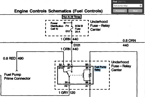
Emergency backup strategy: Remove fuel pump relay. Fused jumper wire to pin for gray wire. (To fuel pump.)
Fuel pump starts running. (Assuming jumped from Hot At All Times source.) Close hood, start truck normally,
drive to day job.
Turn key off, go under hood & physically Disconnect/remove jumper. Listen for the fuel pump to go quiet.
Not recommended if you are feeling forgetful. Best case scenario, if you leave the jumper in place, the pump
will run continuously & completely discharge your battery while you are working. Worst case could be...a lot worse. :0)
We'll get this figured out. More to follow.
Safe travels!
...I'm still not sure where the power went to my orange wire, or where the wire disappears to inside the loom, and I can't find any info besides the svc manual diagram stating it goes to "ecm-b"... I'll try to dig for more info, unless someone can point me in the right direction..?
Though I made sure the relay is cutting pump power on shutoff, I will be SURE to pull my jumper after I park. (I'll be wrapping exposed connector ends in tape. Gonna dive back into this wiring to get it fixed after work tomorrow.
You must be registered for see images attach
")
GOOD troubleshooting. Like the creative use of the hot side of the (unused) heated seat power source.
The only safety-related suggestion would be for you to change from a 30A jumper fuse to a 20A one.
(ie: The same amperage as the ECM B fuse what was originally protecting this circuit. Even so,
I genuinely appreciate that you incorporated a fuse into your ad-hoc troubleshooting jumper. (!)
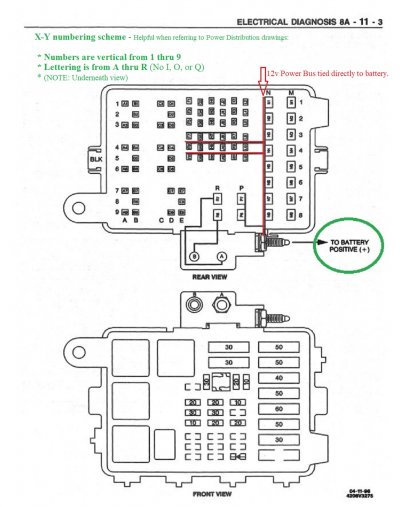
Re: Tracing the break causing the unpowered Orange Wire to this relay socket? We had a flurry of
replies, so maybe you missed my reply #28? Those 3 fuses share a power bus, and if the Horn blows
and the A/C still comes on, then the missing power is between the input of the ECM B fuse and the
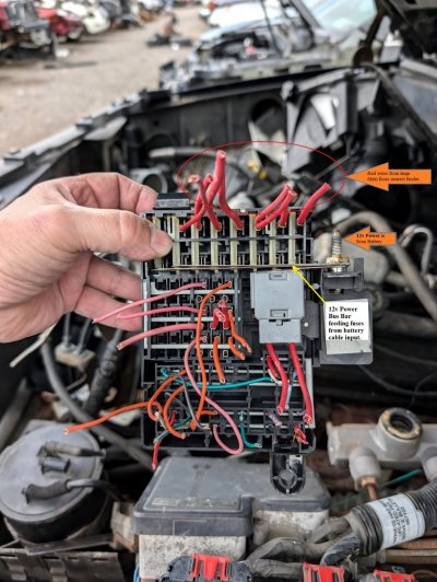
bus itself. On the other hand, if all 3 fuses are dead, then we need to look at the RED wire that's
supposed to be connected to the shared power bus. Etc.
Anyway, I've got to run a couple of errands, but later this evening I'll post a couple of photos from
my fully operational 'known good' '99 C2500, and lay out some things to look for during tomorrow's
fuel pump relay troubleshooting session.
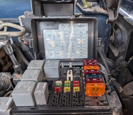
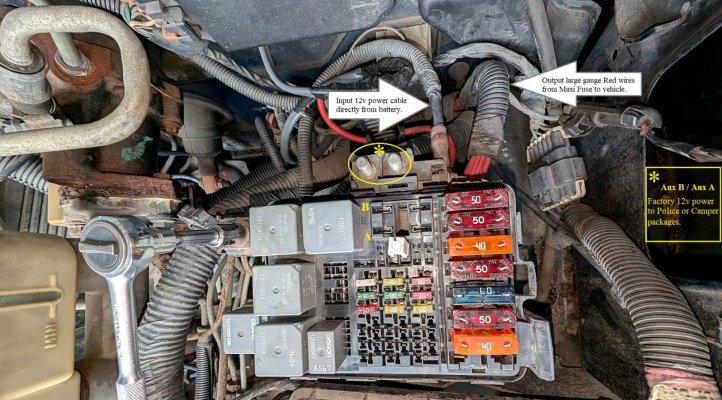
Later on I'll post a couple of underneath photos showing of the fuse block showing how the power/wiring is organized.
...I'm still not sure where the power went to my orange wire, or where the wire disappears to inside the loom, and I can't find any info besides the svc manual diagram stating it goes to "ecm-b"... I'll try to dig for more info, unless someone can point me in the right direction..?
Stating it as concisely as possible, we need to find & fix the open in the wiring between G12 and B1 in the fuse block -- and in order to do so,
we need to go out onto the wiring harness. Including the location of splice S101: